Hopkinson Test

Hopkinson Test

Hopkinson Test requires two identical shunt machines which are coupled mechanically and also connected electrically in parallel. One of them acts as a motor and the other as a generator.

  • The motor takes its input from the supply.
  • The mechanical output of the motor drives the generator and the electrical output of the generator is used in supplying the input to the motor.
  • Thus, the output of each machine is fed as input to the other.
  • When both machines are run on full load, the input from the supply will be equal to the total losses of both machines.
  • Hence the power input from the supply is very small.


This test is also called
(a) regenerative test
(b) back-to-back test
(c) heat-run test

Hopkinson Test Circuit Diagram
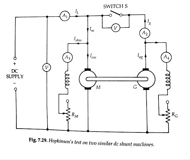
Hopkinson Test 

  • The circuit diagram for the Hopkinson test is shown in Fig. 7.29 machine M is started from the supply as a motor with the help of a starter (not shown).
  • The switch S is kept open.
  • The field current of M is adjusted with the help of field rheostat RM to enable the motor to run at the rated speed.
  • Machine G acts as a generator. Since G is mechanically coupled to M, it runs at the rated speed of M. 
  • The excitation of the generator G is so adjusted with the help of its field rheostat RG that the voltage across the armature of G is slightly higher than the supply voltage.
  • In actual practice, the terminal voltage of the generator is kept 1 or 2V higher than the supply busbar voltage.
  • When this is achieved, that is, the voltage of the generator is equal and of the same polarity as the busbar voltage, the main switch S is closed and the generator is connected to the busbars.
  • Thus, both machines are now parallel across the supply. Under this condition, the generator is said to float. That is, it is neither taking any current from nor giving any current to the supply.
  • Any required load can now be thrown on the machines by adjusting the excitation of the machines with the help of field rheostats

The efficiency of the Machine by Hopkinson Test

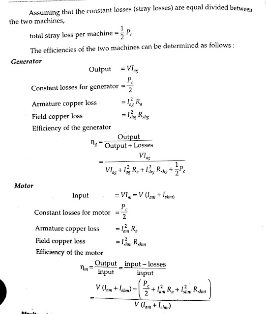
Efficiency of the Machine by Hopkinson’s Test 


efficiency of the Generator And Motor 
The efficiency of the Generator And Motor 


Advantages of Hopkinson Test

  1. The main advantages of using the Hopkinson test for the determination of efficiency.
  2. The total power taken from the supply is meager. Therefore this method is very economical.
  3. The temperature rise and the commutation conditions can be checked under rated load conditions.
  4. stray losses are considered, as both the machines are operated under rated load conditions.
  5. Large machines can be tested at rated loads without consuming much power from the supply.
  6. Efficiency at different loads can be determined.

Disadvantages of Hopkinson Test

The main disadvantage of this method is the necessity of two practically identical machines to be available. Consequently, this test is suitable for manufacturers of large de machines.

Popular posts from this blog

RS Aggarwal Aptitude Book PDF Free Download

RS Aggarwal Aptitude Book PDF Free Download RS Agarwal Aptitude Book PDF Free Download: Quantitative Aptitude by R.S Aggarwal is a standout amongst the most inclining books among the hopefuls getting ready for Bank PO, PO, MBA, RBI, IBPS, CAT, SSC, IAS, PSC, Hotel Management, Railway Recruitment Exams, and other aggressive and placement tests. This book is suggested by different specialists in this field. This book covers relatively every theme which is being requested for the focused exams. On the off chance that you are looking to Download RS Aggarwal Quantitative Aptitude PDF's most recent version with the expectation of complimentary then you appear to be at the correct place.    Download PDF  RS Agarwal Aptitude Book PDF Free Download This book covers Problems on Surds and Indices, Simplification, Numbers and Ages, Pipes and Cisterns, Boats and Streams, Problems on Trains, Simple and Compound Interests, Time and Work, Permutations and Combination, Clocks, Odd Man Out, Heights

Limitations of Terzaghi Theory

Limitations of Terzaghi Theory The value of the coefficient of consolidation has been assumed to be constant.  The distance d of the drainage path cannot be measured accurately in the field. The thickness of the deposit is generally variable, and an average value has to be estimated.  There is sometimes difficulty 1n locating the drainage face, and sometimes thin previous seams that can act as good drainage faces are missed in the boring operations. The equation is based on the assumption that the consolidation is one-dimensional. In the field, the consolidation is generally 3-dimensional. The lateral drainage may have a significant effect on the time rate of consolidation. The initial consolidation and secondary consolidation have been neglected. Sometimes these form an important part of the total consolidation. In actual practice, the pressure distribution may be far from linear or uniform.

Comparison between VSI and CSI

Comparison between VSI and CSI In power electronic systems, inverters are an essential component that converts direct current (DC) into alternating current (AC). There are two main types of inverters used in power electronic systems: Voltage Source Inverters (VSI) and Current Source Inverters (CSI). Both have their own unique advantages and disadvantages, and the choice of which to use depends on the specific application and the desired outcome. Comparisons between voltage source inverters and current source inverters are as follows. In voltage source inverters, the input voltage is maintained constant and the amplitude of the output voltage does not depend on the load. However, the waveform of load current, as well as its magnitude, depends upon the nature of load impedance.  In current source inverters (CSI), the input current is constant but adjustable. The amplitude of output current from CSI is freelance of the load. However, the magnitude of output voltage and its undulation outp