Hysteresis Motor
Hysteresis motor is basically an asynchronous motor with uniform airgap and without de-excitation. This motor may operate from single-phase 3-phase supply, In a hysteresis, the motor torque is produced due to hysteresis and eddy current induced in the rotor by the action of the rotating flux of the stator windings.Stator Construction Of Hysteresis Motor
The stator of a hysteresis motor is similar to that of an induction motor with the basic requirement that it produces a rotating magnetic field. Thus the stator of the motor can be connected to either single-phase supply or 3-phase supply. We know that 3-phase motors produce a more uniform rotating field than single-phase motors. For a single-phase hysteresis motor, the stator winding is of permanent split-capacitor type or of the shaded pole type for very small sizes. In the case of the permanent split-capacitor type, the capacitor should be used with an auxiliary winding in order to produce a uniform field as possible.Rotor Construction Of Hysteresis Motor
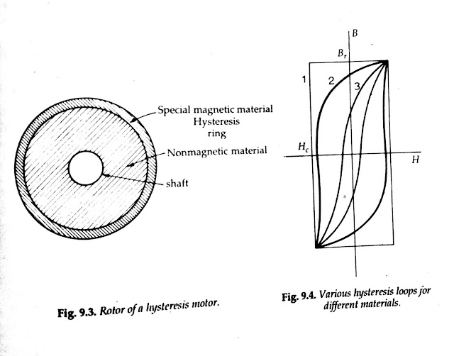
Figure 9.3 shows the rotor of a hysteresis motor. It consists of a core of aluminum or some other nonmagnetic material which carries a layer of special magnetic material. The outer layer has a number of thin rings to form the laminated rotor. In smaller motors, a solid ring may be used. Thus, the rotor of a hysteresis motor is a smooth cylinder and it does not carry any windings (no rotor bars). The ring is made of a special magnetic material such as magnetically hard chrome or cobalt steel having very large hysteresis loop as shown in Fig. 9.4.Operation Of Hysteresis Motor
When a 3-phase supply or a single-phase supply is applied to the stator, a rotating magnetic field is produced. This rotating magnetic field magnetizes the rotor ring and induces poles within it. A uniform cross-section rotor inherently will match the number of stator poles. The induced rotor flux lags behind the rotating stator flux because of the hysteresis loss in the rotor. The angle 8 between the stator magnetic field Bs and the rotor magnetic field B is responsible for the production of torque. The angle o depends only on the shape of the hysteresis loop. It does not depend upon the frequency. For this reason, a magnetic material having a wide hysteresis loop should be used. Thus, the coercive force H, and the residual flux density B, of the magnetic material should be large. An ideal material would have a rectangular hysteresis loop as shown by loop 1 in Fig. 9.4. Ordinary steels are not suitable for a hysteresis motor since their hysteresis loops resemble loop 3 in Fig. 9.4. Cobalt-vanadium type materials are used in hysteresis motors. They have the hysteresis loops according to loop 2 in Fig. 9.4. Such a loop approximates the ideal loop 1.
In addition, the stator magnetic field produces eddy currents in the rotor. These eddy currents produce their own magnetic field. Thus, there is an additional torque on the rotor due to these eddy currents.
The eddy-current loss is given by,
It is seen from Eq. (9.3.2) that t is proportional to the slip. Therefore decreases as the rotor speed increases. When the motor reaches synchronous speed, the slip becomes zero and the torque t becomes zero. The stator current falls off and the rotor acts as a permanent magnet, and the machine runs as a permanent magnet type motor. It is to be noted that the torque t, aids in the starting of the motor.
The electromagnetic torque developed by a hysteresis motor due to hysteresis is given by Eq. (9.3.4). This component of torque remains constant at all rotor speeds until the breakdown torque. Since t, is zero at synchronous speed, the only torque at synchronous speed is the torque T, Thus, at synchronous speed, the induced torque in the motor is proportional to the angle δ between the stator and rotor magnetic fields to a maximum angle set by the hysteresis in the motor.
Torque-speed Characteristic Of Hysteresis Motor
An ideal torque-speed curve for the hysteresis motor is shown by curve 1in Fig. 9.6.
The torque-speed characteristic of a practical hysteresis motor is shown by curve 2 in Fig. 9.6. The departure from the ideal characteristic 1 is due to the presence of harmonics in the rotating field and other irregularities. The torque-speed characteristic of a hysteresis motor is quite different from that of an induction motor. The torque developed by an induction motor becomes zero at synchronous speed, while in an ideal hysteresis motor it is constant at all speeds including synchronous speed. Thus, it is seen from the characteristic that locked rotor, starting and pullout torques are all equal. This is a valuable property in that such a motor can pull into synchronism at high inertia loads.
Applications Of Hysteresis Motor
The hysteresis motor has a very low noise level compared to a single-phase induction motor. This is because it operates at one speed (synchronous speed) and its rotor is smooth (unslotted). With a permanent capacitor stator, the hysteresis motor is the smoothest running, quietest single-phase motor and therefore is preferred for quality sound reproduction equipment like record players, tape recorders, etc. The most common application of hysteresis motor is for electric clocks and other timing devices. With provisions for pole changing in the stator, the motor is multispeed. This motor is made in very small sizes only.Read More


