Power Line Carrier System
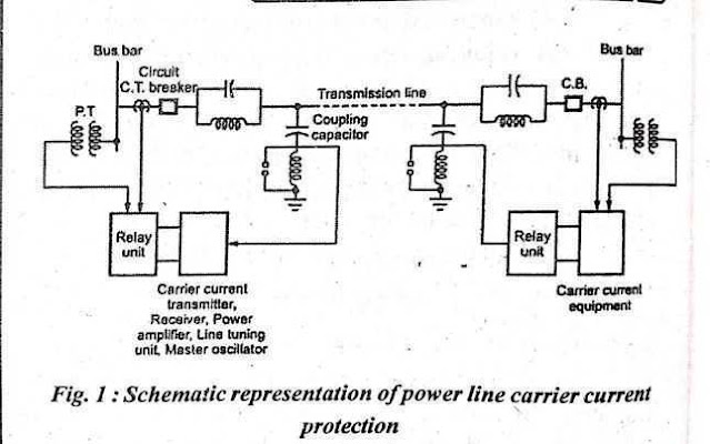
A power line carrier system is used for the protection of transmission lines. The carrier currents with high-frequency range are transmitted and received with the help of transmission lines for protection. The schematic representation of the power line carrier current protection is shown in Fig. (1).
Equipment like transmitter, receiver, line tuning unit, master oscillator, power amplifier, etc. are provided at each end of the transmission line in this carrier's current scheme.
Various blocks in the schematic representation of power line carrier current protection are explained below:
Coupling capacitor
The various carrier equipment described 'above is connected to the transmission line with the help of the coupling capacitor. The capacitive reactance is given by l/WC. Hence carrier frequency, offers less reactance while high reactance for normal power frequency.
It can be seen that the carrier current signals are allowed to pass through this capacitor and enter carrier equipment while power frequency currents are blocked. The inductance connected in series with the coupling capacitor reduces the impedance to a further low value. Thus a condition of resonance is achieved at the carrier frequency.
Line Trap Unit.
This unit is between the busbar and the connection of the coupling capacitor to the line. It consists of a parallel combination of inductance (L) and capacitance (C) acting as a tuned Circuit. This circuit offers low impedance to power frequency currents while offers very high impedance to carrier frequency currents which prevents the high-frequency carrier to enter the neighboring line and carrier flow only in the protected line.
Protection and Earthing of Coupling Equipment
Due to lightning, switching transients, or faults, overvoltage surges are produced on the transmission line. These overvoltages may produce stress on coupling equipment and line trap unit. For protection purposes, the nonlinear resistors are connected across the line trap unit in series with a protective gap.
These resistors with the protection of the gap are connected across the inductor in the coupling unit. The length of the gap is adjusted in such a way that, spark over takes place at a set value of overvoltage. The earth rod is used for is for-earthing of the coupling unit so as to get a low-resistance earth path. The relay room consists of a carrier equipment panel which 1s connected to the station earthing system.
Electronic Equipment
Following electronic equipment are generally used at each end of the line,
(a) Transmitter unit
(b) Receiver unit
(c) Frequency spacing
(d) High-Frequency signal modulation
(a) Transmitter Unit:
Normally the frequencies with a range from 50 to 500 kHz are employed in various frequency bands with each having specific bandwidth. The oscillator is used for the generation of cancer frequency and it is tuned for a particular frequency that is chosen for a particular application.
Sometimes a crystal oscillator may also be used which gives particular bandwidth after selecting a particular type of crystal. Voltage stabilizers are employed for maintaining the oscillator output voltage constant. The losses in the transmission path between the transmitter and receiver at the remote end of the line are overcome with the help of an amplifier which increases the level of the signal to be transmitted.
If the weather is fairly reasonable then the attenuation is of the order of 0.1 dB/kHz at 80 kHz which increases 0.2 dB/km at 380 kHz. If we‘ consider 250 km line then the output of the power amplifier is about 20 W. For a particular bandwidth, the amplifier should give maximum power. The interconnection between the oscillator and amplifier is done through the control circuit.
(b) Receiver unit
The signal is reduced to a safe value with the help of an attenuator. The undesired signals which are signals from subsequent sections or spurious signals are prevented by using a bandpass filter. The matching element matches the impedance of the transmission line and receiving section. The undesired signals are generated either by short circuits or radio interferences.
The malfunctioning of this unit is avoided due to the noise signals by using the set value above 2 milliwatts which is above the noise level. If the carrier signals have a power level of 20 W and the receiver unit is set. at a higher level of 5 milliwatts then the operation is unaffected by spurious signals. For avoiding overloading, the signals should be attenuated before applying g it to the amplifier detector.
(c) Frequency Spacing:
The subsequent line sections use various frequencies. The carrier signals are prevented from entering the next section by wave traps. The filters from the receiving unit filter other frequencies. The frequency and bands of various sections are properly coordinated.
(d) High-Frequency signal Mod:
For the modulation of power frequency signals, the modulator is used. The signal after modulation is passed to the amplifier and then transmitted through the coupling unit. From the half-cycle line currents, the required blocks of carrier signals are generated with the help of an oscillator. The level of line current at which the oscillator generates these carrier blocks should be theoretically constant but practically there is a critical minimum current. The modulation of line current into high-frequency carriers is shown in the current.
