Carrier current protection
Carrier current protection is the most widely used scheme for the protection of transmission lines. This protection is used for the protection of EHV and UHV Power lines.In this scheme carrier currents of the high-frequency range are transmitted and received with the help of transmission lines for protection.
- As the development in the power system is growing and large interconnected systems becoming very essential for high-speed protective schemes, carrier current protection is becoming suitable for EHV and UHV power lines.
- They are faster and superior to distance protection schemes.
- They are also economical and provide both primary and backup protection.
- In conventional time-stepped distance protection, circuit breakers at both ends of the line don‘t trip simultaneously when a fault occurs at one end of the end zones of the protected line section.
- This causes instability in the system sometimes.
Methods of Carrier Current Protection
The different methods of current carrier protection and the basic form of the carrier current protection are- Directional Comparison protection
- Phase Comparison Protection
Directional comparison method
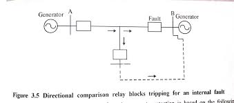
Upon the occurrence of a fault either in the protected section of the line or in a nearby section, non-directional fault-detector relays are actuated at each line terminal through which power is fed to the fault. Each fault detector relay turns on the carrier current transmitter at its own terminal. If the directional relay at any terminal shows that the fault power is flowing into the protected line section, that relay will tum off the carrier current transmitter. The presence of a carrier on the line serves to block tripping at all terminals. For an external fault, power will flow out of the line at one terminal and a carrier signal transmitted from the terminal will prevent the tripping at the other terminals, where power is flowing in.On the other hand, for an internal fault power will usually flow into the line from all terminals, which results in the turn off of all carry transmitters, and the relays at all terminals will trip simultaneously. The carriers are transmitted only upon the occurrence of a fault and are used only to prevent tripping in the event of an external fault. Therefore, the possible short-circuiting of the carrier channel by an internal fault cannot block the operation of the relays to clear the fault.
Phase Comparison Method
In situations where there is no communication between circuit ends, a comparison between relative phase angles is often possible. The most widely used protection of this kind is the phase comparison carrier current protection system in which alternate half cycles of the current of each end of the protected circuit are modulated with a carrier signal and transmitted over the power line.
Normally, the phase angle between the currents at both the ends of the protected \ine will be such that the comparator is inoperative (i.e., the phase displacement is 0°) whereas for an internal fault the angular displacement will be nearly 180°.
The schematic diagram outputs of the phase comparison are shown in figure 3.6. If the current are in phase, there will be no fault in the protected section. If two currents are 180° out of phase, a fault in the line is indicated.
At each end of the protected line section line trap is installed in series with the line conductor. The line trap is a parallel resonant circuit tuned to the carrier frequency. It helps in keeping the carrier signal confined to the protected line section. The line trap offers very high impedance to the carrier signal and low impedance to the power frequency current. There are carrier transmitters and receivers at both ends of the protected line. Both transmitter and receiver are connected to the power line through a coupling capacitor so as to withstand high voltage and be grounded through an inductance. The coupling capacitor offers very high impedance to power frequency current and low impedance to carrier frequency current. It consists of a porcelain-clad, oil-filled stack of capacitors connected in series. The inductance offers low impedance to power frequency current and offers a high impedance to carrier frequency current. The transmitter and receiver are insulated from the power line and it is effectively grounded at power frequency current.
A carrier frequency, both transmitter, and receiver are connected to the power line and are insulated from the ground.
Transmission of carrier signal either by phase-earth coupling (one phase conductor with earth return) or phase-phase coupling (two-phase conductors). The performance of phase to phase coupling is better as compared to phase-earth coupling.
Through the coupling capacitor, half-cycle blocks of carrier signals are injected into the transmission line. Fault detectors are also installed in the lines so as to control the carrier Signal. Fault detectors Operate only during faults.
Two stations A and B having a voltage output of the summation network of 180° out Of Phase during normal conditions as shown in figure 3.6. This is because of the reason that the CT. connections at the two ends are reversed. The transmission of the carrier signal takes place only during a positive half cycle of the network output.
Advantages of carrier current protection
The advantage of carrier current protection is following as
- It is capable of providing high-speed protection for the whole length of the protected line.
- The carrier signal can be used either to prevent or initiate the tripping of a protective relay.

