Digital Relay Block Diagram

Digital Relay


A digital relay is an electronic device that uses digital circuitry to perform the functions of an electromechanical relay. Digital relays use microprocessors and other digital components to detect and respond to electrical signals and can offer advanced features such as programmability and communication capabilities. They are commonly used in power systems, industrial control systems, and other applications where precise control of electrical circuits is required.

Digital Relay Block Diagram

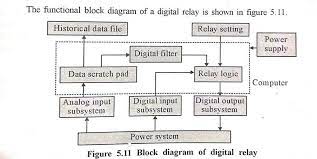
The power supply unit provides the necessary power to the whole relay from the power system required inputs are applied to the analog input subsystem and to the digital input subsystem. According to the relay setting the relay logic provides the output to the digital output subsystem. The historical data file is used to store the previous records of the digital relay. As the desired output from the digital relay is received by the circuit breaker, the circuit breaker performs the required operation. For a three-phase system, the block diagram of the digital relay 

Digital Relay Block Diagram


The Digital relay that is in use for protection consists of the following subsystems:

(a) Analog input subsystem
(b) Digital input subsystem
(c) Digital output subsystem
(d) A processor along with RAM (called Data Scratch Pad), main memory (Historical data file), and power supply unit.

The relaying voltages at 110V or 50V and currents at 5A or 1A are first passed through an isolation transformer. Relay settings are stored in the EEPROM (Electrically Erasable Programmable Read-Only Memory). 

The relaying program will be located in the ROM (Read Only Memory) and the RAM (Random Access Memory) will be used for storing sampled quantities and intermediate products are the relaying algorithm.
Popular posts from this blog

RS Aggarwal Aptitude Book PDF Free Download

RS Aggarwal Aptitude Book PDF Free Download RS Agarwal Aptitude Book PDF Free Download: Quantitative Aptitude by R.S Aggarwal is a standout amongst the most inclining books among the hopefuls getting ready for Bank PO, PO, MBA, RBI, IBPS, CAT, SSC, IAS, PSC, Hotel Management, Railway Recruitment Exams, and other aggressive and placement tests. This book is suggested by different specialists in this field. This book covers relatively every theme which is being requested for the focused exams. On the off chance that you are looking to Download RS Aggarwal Quantitative Aptitude PDF's most recent version with the expectation of complimentary then you appear to be at the correct place.    Download PDF  RS Agarwal Aptitude Book PDF Free Download This book covers Problems on Surds and Indices, Simplification, Numbers and Ages, Pipes and Cisterns, Boats and Streams, Problems on Trains, Simple and Compound Interests, Time and Work, Permutations and Combination, Clocks, Odd Man Out, Heights

Limitations of Terzaghi Theory

Limitations of Terzaghi Theory The value of the coefficient of consolidation has been assumed to be constant.  The distance d of the drainage path cannot be measured accurately in the field. The thickness of the deposit is generally variable, and an average value has to be estimated.  There is sometimes difficulty 1n locating the drainage face, and sometimes thin previous seams that can act as good drainage faces are missed in the boring operations. The equation is based on the assumption that the consolidation is one-dimensional. In the field, the consolidation is generally 3-dimensional. The lateral drainage may have a significant effect on the time rate of consolidation. The initial consolidation and secondary consolidation have been neglected. Sometimes these form an important part of the total consolidation. In actual practice, the pressure distribution may be far from linear or uniform.

Comparison between VSI and CSI

Comparison between VSI and CSI In power electronic systems, inverters are an essential component that converts direct current (DC) into alternating current (AC). There are two main types of inverters used in power electronic systems: Voltage Source Inverters (VSI) and Current Source Inverters (CSI). Both have their own unique advantages and disadvantages, and the choice of which to use depends on the specific application and the desired outcome. Comparisons between voltage source inverters and current source inverters are as follows. In voltage source inverters, the input voltage is maintained constant and the amplitude of the output voltage does not depend on the load. However, the waveform of load current, as well as its magnitude, depends upon the nature of load impedance.  In current source inverters (CSI), the input current is constant but adjustable. The amplitude of output current from CSI is freelance of the load. However, the magnitude of output voltage and its undulation outp